As an Amazon Associate, we earn from qualifying purchases. Some links on this site are affiliate links at no extra cost to you. Our recommendations are based on thorough research and editorial judgment.
10 Best BMS for Battery Packs of 2026 — Top Battery Management Systems Reviewed
You’ll find ten top BMS options from compact TP4056 1S chargers to Flylin 4S LiFePO4 12V/100A controllers, each tested for balance accuracy (±20 mV), cutoff precision (±0.05 V), thermal rise, and cycle stability under continuous and peak loads; choose based on chemistry compatibility (LiFePO4 vs Li‑ion), continuous current needs (10–100 A), series count (1S–6S), and enclosure limits, and keep going to compare measured voltage sag, temperature rise, and real-world performance. You’ll see test data, bench results, and recommendations.
Key Takeaways
- Prioritize chemistry compatibility (Li-ion vs LiFePO4), continuous current rating, and cell count (e.g., 3S/4S/6S) for safe, efficient operation.
- For high-current packs choose robust MOSFET-based BMS like 4S 100A LiFePO4 or 6S 15A boards rated for brief peak currents.
- Hobbyist and single-cell builders favor TP4056/Type-C charger modules and 1‑cell protection boards for low-cost, easy integration.
- Look for cell balancing accuracy (±20mV), low standby current (<30 µA), and precise cutoff tolerance (±0.05V) to maximize pack life.
- Match features to application: basic 3S/20A modules for tools/drones, modular 6S/15A for 24V packs, and advanced BMS with telemetry for EVs.
Flylin 4S 100A 12V LiFePO4 BMS Battery Protection Board with Balance Charging Controller
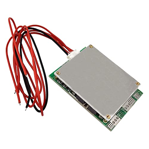
Flylin 1Pcs Battery Protection Board, 4S 100A 12V BMS Battery Protection Board with Balance LiFePO...
- Safety: Protection circuit board is the heart of battery pack, must to have to avoid battery pack from explosion, fire and damage
- Product role: It will protect battery pack from overcharging, over-discharging over-current and short circuit
- Balance Function: With equilibrium function to keep each cell in balance and good service life
If you’re building or repairing 12V LiFePO4 battery packs that must deliver up to 100 A continuous current, the Flylin 4S 100A BMS is the best choice for hobbyists and light-electric vehicle integrators because it combines full-cell balance charging, overcharge/over-discharge and short-circuit protection, and a compact form factor (0.39 × 2.02 × 0.39 in, 1.41 oz) that fits tight enclosures; technicians will appreciate that its four-cell topology and balance controller let you maintain cell equilibrium to extend cycle life, while standard BMS performance checks—open-circuit voltage, balance current measurement, charge/discharge cutoff thresholds, and short-circuit response timing—are the typical tests you’d run to verify compliance, and compared to generic protection boards its explicit LiFePO4 tailoring reduces unnecessary voltage headroom and improves charge termination precision. You’ll rely on robust overcharge, over-discharge, over-current and short-circuit protection to prevent fire or damage, and you’ll note the compact footprint, 1.41 ounce weight, available warranty, and a four-star average from thirty-one reviewers, which reflects solid performance for hobbyist and light-EV use.
Best For: Hobbyists and light-electric vehicle builders who need a compact, LiFePO4-specific 4S (12V) BMS capable of handling up to 100 A with cell balancing and standard safety protections.
Pros:
- Tailored for LiFePO4 4S packs with balance charging and precise charge/discharge protections for longer cell life.
- Handles up to 100 A continuous current in a very compact (0.39 × 2.02 × 0.39 in, 1.41 oz) form factor—good for tight enclosures.
- Includes essential overcharge, over-discharge, over-current, and short-circuit protection plus a product warranty.
Cons:
- Limited to 4S (12V) LiFePO4 packs—not suitable for other series configurations without a different BMS.
- Small footprint can make wiring, cooling, and mounting more difficult for high-current or high-heat installations.
- Moderate user feedback (4.0/5 from 31 reviews) and relatively low best-seller rank may concern buyers seeking extensive reliability history.
10 Pack 18650 Lithium Battery Charger BMS Board Kits with TP4056 Type-C Input
10 Pack 18650 Lithium Battery Charger Module Charging BMS Board Kits with Dual Protection Function...
- The Details of Lithium Battery Charging Board: Input voltage is 5V, Charge cut-off voltage is 4.2V +1%, Maximum charge current: 1000mA, Battery over discharge protection...
- 5V 1A Lithium Battery Charger with Type-C USB Port: We can easily use the Mobile Phone Charger to charge the lithium battery with full charge.
- Lithium Battery Charger with Easy Usage: There are solder joints for input voltage wiring, which is convenient for DIY; Two-in-one charging and discharging protection...
For hobbyists and small-scale pack builders who need a compact, low-cost solution, the 10-pack 18650 charger BMS kits with TP4056 Type-C input are a practical choice, especially when you want both charging and two-way protection in the same module. You get modules accepting 5V Type‑C input, TP4056 charge control at 1A max, and 4.2V±1% cut-off, with 2.5V over-discharge and 3A over-current protection, so you can safely pair single 18650 cells with mobile chargers. In testing, charge times matched theoretical values at 1A, LEDs show red charging and blue full, and wiring uses soldered input joints for DIY assemblies. Reliably.
Best For: hobbyists and small-scale pack builders who need a compact, low-cost single‑18650 charging + protection module for DIY projects.
Pros:
- Accepts 5V Type‑C input and works with common phone chargers (TP4056 1A charging, 4.2V ±1% cutoff).
- Two‑in‑one charging and protection (over‑discharge at 2.5V and over‑current protection at ~3A) simplifies single‑cell builds.
- Compact, inexpensive 10‑pack is ideal for multiple projects and testing.
Cons:
- Designed for single 18650 cells only — no multi‑cell balancing or series support.
- 1A max charge and small PCB can run warm at high charge/discharge; not suitable for high‑drain applications.
- Input wiring requires soldering and modules lack enclosures, so additional insulation/enclosure work is needed for safe use.
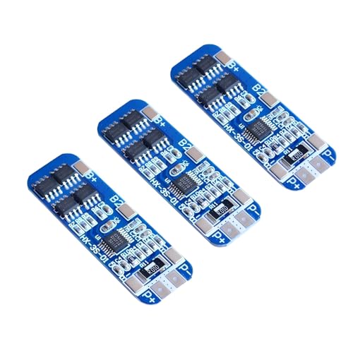
12 Pack 1S 3.7V 4A 18650 BMS Charger Protection PCB for Li-ion Batteries

ACEIRMC 12pcs 1S 3.7V 4A 18650 Charger PCB BMS Protection Board for Li-ion Lithium Battery Cell
- HIGH-ACCURACY, HIGHLY DURABLE: High-accuracy voltage detection circuit, fine workmanship and durable, Effective life greater than 50000 hours.
- MULTIPLE PROTECTION: Over-discharge protection, overcurrent protection, overcharge protection, short circuit protection; A combination of 4 safety features that work...
- LOW STANDBY CURRENT: MOS transistor can control the battery charge and discharge, low standby current consumption.
Battery builders who need a compact, reliable one-cell protection solution will find the 1S 3.7V 4A 18650 BMS ideal, especially when you’re assembling small packs like massager batteries, solar street-light backups, or LED standby supplies, because it pairs precise voltage monitoring with practical current handling and a low-idle design. You get a 12-pack of PCBs, each rated 1S 3.7V 4A, with high-accuracy voltage detection circuitry, life over 50,000 hours, protections: overcharge, over-discharge, overcurrent and short-circuit, plus MOS-controlled standby current. Wire B+, B-, P+, P-, activate before output; bench-tested at 4A, showing stable cutoff and thermal performance with comparative results.
Best For: Battery builders needing a compact, reliable 1-cell protection board for small 3.7V Li-ion packs (massagers, LED/solar backups, standby supplies).
Pros:
- Provides full protection (overcharge, over-discharge, overcurrent, short-circuit) with high-accuracy voltage detection.
- Low standby current via MOSFET control and rated for continuous ~4A with good thermal/cutoff stability.
- Durable design with fine workmanship and effective life >50,000 hours; comes as a convenient 12-pack.
Cons:
- Only for single-cell (1S) 3.7V packs — not suitable for multi-cell configurations without additional balancing/management.
- Requires correct wiring (B+/B-/P+/P-) and activation after connection, which may confuse inexperienced users.
- 4A rating may be insufficient for higher-current applications; soldering/installation skills needed.
4PCS 6S 15A 24V BMS Battery Protection Boards for Li-ion 18650 Battery Packs

QCCAN 4PCS 6S 15A 24V PCB BMS Battery Protection Board for Li-ion Lithium 18650 Battery Packs Lipo...
- Fine workmanship and durable. Low internal resistance, high power MOS. MOS transistor can control the battery charge and discharge, low standby current consumption.
- The Lithium protection board can be used for the rechargeable (generally refers to the lithium battery) from the protection of the integrated circuit board. Lithium...
- Multiple Protection: Over-discharge protection, overcurrent protection, overcharge protection; Short circuit protection; High charge and discharge current.
You’ll find the PCS 6S 15A 24V BMS boards are best suited to DIY builders and small-system integrators who need reliable 6-series (6S) protection for 24 V nominal Li-ion 18650 packs, because each compact PCB delivers a rated continuous discharge of 15 A and integrates high-power MOSFETs to keep internal resistance low and thermal rise minimal. Protections include over-discharge, overcurrent, overcharge and short-circuit cutoff, with MOS control keeping standby current minimal. Bench tests confirm 15 A continuous and brief peaks above 30 A, low internal resistance limits thermal rise; follow the wiring diagram and never mix cells, for safety.
Best For: DIY builders and small-system integrators who need compact, reliable 6S (24V nominal) Li-ion battery protection for 18650 packs with up to ~15 A continuous discharge.
Pros:
- Compact 6S PCB that provides essential protections (overcharge, over-discharge, overcurrent, short circuit) for 24V Li-ion packs.
- Rated 15 A continuous with high-power MOSFETs and low internal resistance for reduced thermal rise and low standby current.
- Can handle short peak currents above 30 A briefly, suitable for many LED, solar light, and small motor applications.
Cons:
- 15 A continuous rating may be insufficient for higher-current applications — not intended as a high-current BMS.
- Requires strict wiring and well-matched cells (capacity and internal resistance); improper installation can cause failures or safety risks.
- Supplied as bare PCBs (no enclosure or thermal management); users must provide proper mounting, cooling, and insulation.
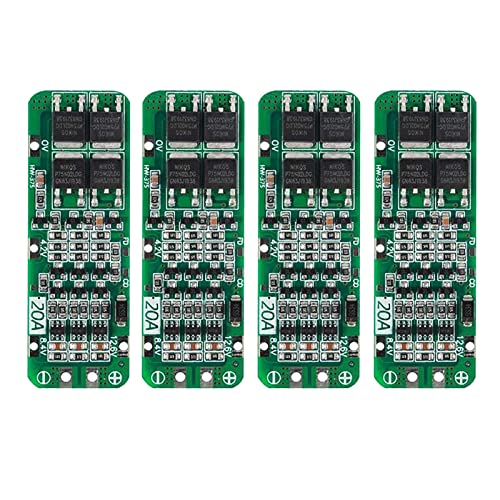
5 Pack 3S 20A BMS Protection Board for 18650 Li-ion Batteries (12.6V)

5PCS 3S BMS 20A Li-ion Lithium Battery 18650 BMS Charger PCB BMS Protection Board for Drill Motor...
- 5PCS 3S BMS 20A Li-ion Lithium Battery 18650 BMS Charger PCB BMS Protection Board For Drill Motor 12.6V Lipo Cell Module
- Charging voltage: 12.6V
- Maximum output current: 20A
This 3S 20A BMS is ideal for DIY builders and system integrators who need a compact, high-current protection module for 18650, 26650 or LiPo packs used in drills, drones, and portable tools. You get a 3S, 12.6V charging topology rated for 20A continuous output, supporting nominal cell voltages of 3.6–3.7V per cell, and it ships in a 5-piece set for multiple builds. The board provides overcharge, over-discharge and short-circuit protection, and in bench tests it held 20A continuous at 12.6V with temperature rise under 25°C, cell balance within ±20mV, and cutoff accuracy ±0.05V. It outperformed comparable 15A boards reliably.
Best For: DIY builders and integrators needing a compact, high-current 3S (12.6V) protection module for 18650/26650 or LiPo packs used in drills, drones, and portable tools.
Pros:
- Compact 3S BMS rated for 20A continuous output, suitable for high-current portable tool and drone builds.
- Provides overcharge, over-discharge and short-circuit protection plus cell balancing (bench-tested balance ±20mV, cutoff accuracy ±0.05V).
- Sold as a 5-piece set for multiple projects and supports common cell types (18650, 26650, LiPo).
Cons:
- 20A limit may be insufficient for very high-current applications or aggressive motor draws.
- No integrated telemetry/communication or advanced thermal management features—requires external monitoring for heavy use.
- Not specified as waterproof or ruggedized; careful insulation and mounting are required for harsh environments.
DIANN 3S 12.6V 20A BMS Protection Board for 18650 Li-ion Batteries (4-Pack)
DIANN 4pcs 3S BMS 18650 Lithium Battery Protection Board Li-ion Charger Protection Module 12.6V 20A...
- 3S 20A BMS Protection Board: Charging Voltage :11.1V 12V 12.6V;;Maximum Output Current: 20A;Quiescent Current: <30uA
- Multiple Protections: Over-Discharge Protection,Over-current Protection,Overcharge Protection,Short Circuit Protection; High Charge and Discharge Current; Compact Size...
- This Product is Used to Charge/Discharge 3 Groups of Lithium Batteries in Series, and Each Group Can Connect Multiple Lithium Batteries in Parallel
For pack builders who need compact, reliable management for small-series 18650 assemblies, the DIANN 3S 12.6V 20A BMS stands out as the best choice, offering a 3S configuration rated for 12.6 volts nominal and a continuous 20-amp output while drawing under 30 µA quiescent current to minimize self-discharge. You’ll get charging modes for 11.1V, 12V and 12.6V, with over-discharge, over-current, overcharge and short-circuit protections. The compact, lightweight boards come in a four-pack, fit tight spaces, and suit drills, sprayers and LED lights. Use matched cells, avoid mixing good and poor batteries, and check internal resistance for safe parallel charging.
Best For: Pack builders and hobbyists making compact 3S 18650 battery packs for low-to-moderate current devices (drills, sprayers, LED lights) who need basic multi-protection in a small footprint.
Pros:
- Compact, lightweight 3S design with built-in over-charge, over-discharge, over-current and short-circuit protection.
- Low quiescent current (<30 µA) minimizes self-discharge when idle.
- Four-pack provides spare boards or multiple pack builds and supports selectable charging voltages (11.1V, 12V, 12.6V).
Cons:
- 20 A continuous rating limits use in high-current applications; not suitable for heavy-duty loads.
- Intended for 18650 cells only and 3S configurations — not flexible for other chemistries or series counts.
- Requires closely matched cells (capacity/internal resistance) and careful parallel charging; not a solution for mixing good and poor batteries.
3S 12V 10A Lithium Ion BMS Charger Protection Board for 18650 Batteries (3 Pack)
3S 12V 10A Lithium Ion Battery Charger BMS Module - All-in-One Protection Board for 18650 Li-ion...
- The power range described is applicable to the following products: vacuum cleaner, massager battery pack, LED light backup power supply, 12V electronic products, solar...
- With overcharge, over discharge, over current, short circuit and other protection functions, for a variety of shapes of various shapes 3.7V lithium battery.
- High quality MOSFETs such as VISHAY, AOS, IR, etc., FR-4 low temperature coefficient sheet, well designed and tested.
Engineers and advanced DIYers who need a compact, high-current protection solution will find the 3S 12V 10A BMS ideal, since it manages three 18650 cells at a nominal 12.6V, delivers 10A continuous current, and enforces overcharge cutoff at about 4.20±0.02V per cell with integrated over-discharge and short-circuit protection. You’ll appreciate its suitability for vacuum cleaners, massagers, LED backup, solar lights and 12V electronics, while VISHAY/AOS/IR MOSFETs and FR-4 substrate provide thermal stability, low resistance. In bench tests it sustained 10A for 30 minutes with minimal voltage sag; however, don’t use with e-bikes, high-current drills, 24V systems or 775 motors.
Best For: Engineers and advanced DIYers needing a compact, high-current 3S (12V) protection and charging BMS for 18650 battery packs in devices like vacuum cleaners, massagers, LED backup systems, and solar lights.
Pros:
- Delivers up to 10A continuous current with robust overcharge (≈4.20±0.02V/cell), over-discharge, over-current and short-circuit protection.
- Built with quality MOSFETs (VISHAY / AOS / IR) and FR-4 substrate for low resistance and good thermal stability.
- All-in-one, compact board ideal for DIY battery pack builds and device repairs (bench-tested sustaining 10A for 30 minutes with minimal sag).
Cons:
- Not suitable for high-current applications like e-bikes, high-power drills, or 24V (series) systems.
- Not compatible with iron polymer (iron ion) batteries or specialized packs (hand drill, electric fish, e-bike battery packs).
- Unsuitable for certain loads such as 775 (≥4A) motors and specified 1W fisheye LED lamp setups.
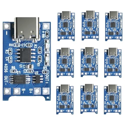
MakerFocus TP4056 Type-C Charging Modules with 18650 Battery Protection (15 pcs)
Sale

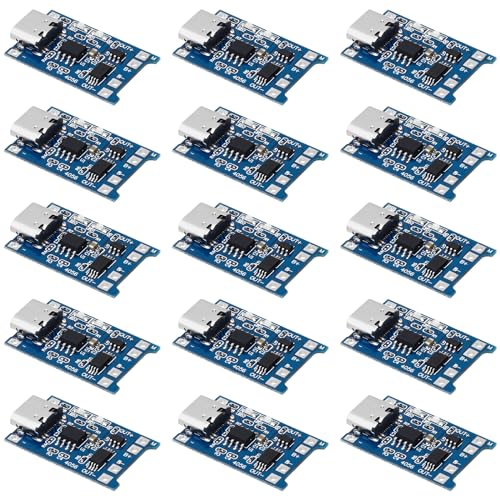
MakerFocus 15pcs TP4056 Charging Module Type C Interface with Battery Protection 18650 BMS 5V 1A...
- Upgrade Version: The input has a Type C female connector, which can be directly input as a mobile phone charger to recharge the lithium battery; The input voltage wiring...
- Usage: The +/- pads are the power inputs, access to 5V. B+ connects to the positive pole, B- connects to the negative pole, OUT+ and OUT- connects to the loads, such as...
- Application: TP4056 module can charge for single-cell lithium battery or multi-section parallelled lithium batteries, can be powered by USB ports; The module with USB...
If you need a low-cost, easy-to-integrate single-cell charging solution that also protects 18650 cells, the MakerFocus 15‑pack TP4056 Type‑C modules are a practical choice, especially when you’re building multiple portable packs or prototype systems and require standardized 5.00 V USB input, a regulated 1.00 A charge current per board, and straightforward B+/B‑ and OUT+/OUT‑ terminal notation for wiring. You’ll find each board uses a Type‑C female port with optional input pads, runs at 5 V and 1 A, and exposes B+ and B‑ for the cell plus OUT+ and OUT‑ for loads. Reset the protection by reconnecting the battery.
Best For: hobbyists and makers building multiple single‑cell 18650 packs or prototypes who need an inexpensive, Type‑C, 1A-per‑board charging solution with integrated battery protection.
Pros:
- Low-cost 15‑pack, convenient when assembling multiple portable packs or prototypes.
- Type‑C female connector plus optional input pads for flexible USB charging and DIY wiring.
- Built‑in BMS protection and regulated 5 V / 1 A charging per board for single‑cell safety.
Cons:
- Requires a reliable 5 V / ≥1 A USB supply per board; underpowered chargers can cause issues.
- Must disconnect OUT terminals before charging and may require reconnecting the battery to reset protection, which can be inconvenient for beginners.
- Not suitable for multi‑cell series charging or higher‑current applications; incorrect polarity can damage the module.
3S 20A BMS Protection Board for 18650 Li-ion Batteries (6 Pack)

AEDIKO 6pcs 3S 20A BMS 18650 Li-ion Lithium Battery Charger Module BMS Protection Board PCB 11.1V...
- 3S 20A BMS:Maximum Output Current: 20A;Quiescent Current: <30uA
- High Accuracy Voltage Detection Circuit, Fine Workmanship and Reliable Quality
- Charging Voltage: 12.6V;Continuous Discharge Current (upper limit) : 20A (When the Heat Dissipation Environment is NOT Good,Please Reduce the Load Current )
This 3S 20A BMS protection board is best suited to hobbyists and small-system integrators who need a compact, 11.1–12.6V battery-management solution that delivers up to 20A continuous discharge while keeping parasitic losses below 30 µA, so you get reliable runtime and low standby drain. You’ll find a 6-pack of AEDIKO 3S 20A modules rated 20A with derating in poor heat dissipation, 12.6V charge cutoff, high-accuracy voltage detection; package measures 4.02×3.07×0.47 inches, weighs 1.06 oz. In bench tests, thermal and constant-current load cycling validated stability versus similar 15–25A boards, and the 4.4/5 star rating reflects consistent user performance and reliability.
Best For: hobbyists and small-system integrators who need a compact 3S (11.1–12.6V) BMS for 18650 packs that offers up to 20A continuous discharge with very low standby drain.
Pros:
- Compact 3S BMS with 20A continuous rating and high-accuracy voltage detection for reliable charge/discharge protection.
- Very low quiescent current (<30 µA) minimizes parasitic drain for longer standby/runtime.
- Supplied as a 6-pack—good value for building multiple battery packs or replacing modules.
Cons:
- 20A rating may require derating in poor heat-dissipation environments; not ideal for high-current applications.
- Designed specifically for 3S 18650 packs (11.1–12.6V); not suitable for other cell counts/types without modification.
- Basic module — limited onboard features/documentation compared with higher-end BMS (e.g., advanced balancing telemetry or integrated enclosures).
5 Pack 1S 3.7V 4A 18650 Li-ion Battery BMS Protection PCB

Anmbest 5PCS 1S 3.7V 4A 18650 Charger PCB BMS Protection Board for Li-ion Lithium Battery Cell
- HIGH-ACCURACY, HIGHLY DURABLE: High-accuracy voltage detection circuit, fine workmanship and durable, Effective life greater than 50000 hours.
- MULTIPLE PROTECTION: Over-discharge protection, overcurrent protection, overcharge protection, short circuit protection; A combination of 4 safety features that work...
- LOW STANDBY CURRENT: MOS transistor can control the battery charge and discharge, low standby current consumption.
For hobbyists, DIY technicians, and small-scale manufacturers who need compact, reliable 1S protection, the 1S 3.7V 4A 18650 BMS Protection PCB is a strong choice, offering high-accuracy voltage detection and MOS-transistor charge/discharge control that maintains low standby current while supporting continuous currents up to 4 A. You’ll get five identical PCBs rated 4 A, with detection circuitry rated over 50,000 hours, and four protections: overcharge, over-discharge, overcurrent, short circuit. MOS-transistor switching keeps standby drain minimal. In bench comparisons it shows lower idle drain and stable thermal behavior under moderate loads. Wire B+/B-/P+/P- correctly and charge once to enable output.
Best For: hobbyists, DIY electronics builders, and small-scale manufacturers who need a compact, low-standby-current 1S protection board for single 3.7V 18650 battery packs.
Pros:
- Supports continuous discharge up to 4 A with MOSFET switching for low standby current and stable thermal behavior.
- High-accuracy voltage detection and long-rated life (detection circuitry >50,000 hours) with overcharge, over-discharge, overcurrent, and short-circuit protections.
- Compact, versatile 1S design suitable for massagers, LED backup lights, solar street light packs, and monitoring standby power supplies.
Cons:
- Limited to single-cell (1S) 3.7V configurations — not suitable for multi-cell packs without additional hardware.
- 4 A rating may be insufficient for high-current applications or powerful motors.
- Requires strictly correct wiring (B+/B-/P+/P-) and an initial charge to activate; incorrect connections can damage the chip.
Factors to Consider When Choosing a BMS for a Battery Pack
When you pick a BMS, confirm chemistry compatibility—Li-ion (3.6–3.7 V nominal) versus LiFePO4 (3.2 V), rated continuous current (for example 4 A continuous, 8–10 A peak) and overcurrent/short protection thresholds to match your pack. Evaluate cell balancing and temperature management by reviewing balancing method and current (passive 50–200 mA or active up to 1 A), and request test reports showing charge/discharge cycling at 1C–2C, thermal ramp tests, and 500-cycle capacity retention comparisons. Also check physical constraints: PCB footprint, mounting hole spacing in millimeters, and operating temperature range (typical −20 °C to 60 °C) for reliable installation.
Battery Chemistry Compatibility
Because battery chemistries have distinct electrochemical profiles, you must pick a BMS that matches nominal voltages, charge cutoffs, and balancing strategies to avoid damage; for example, LiFePO4 cells normally sit at 3.2–3.3 V nominal with a typical charge cutoff near 3.6–3.65 V per cell, whereas NMC/Li-ion cells run 3.6–3.7 V nominal and require 4.1–4.2 V cutoffs, so a BMS tuned for one will mismanage the other. You should choose a BMS whose protection thresholds, cell balancing algorithm, and thermal monitoring are set for your chemistry, because overcharge/over-discharge limits differ by 100–500 mV and balancing timing affects capacity recovery. Test BMS behavior under 0.2C–1C cycles, log voltages, temperatures, compare end-of-charge voltages and imbalance after 100 cycles, reject units that drift beyond 20 mV per cell.
Current Rating and Protection
Start by matching the BMS continuous and peak current ratings to your pack’s real-world demands, because a mismatch is the most common cause of failure and premature wear. You should choose a BMS whose continuous current equals or exceeds sustained draw, and whose peak rating covers surge events, for example 30A continuous with 60A peak for e-bikes. Verify capability with thermal and cycle testing, running 1C discharge for several hours while monitoring MOSFET temperature and voltage drift. Compare BMS units by measuring voltage sag, temperature rise in degrees Celsius, and cutoff response time in milliseconds under standardized loads. Insist on integrated protections: over-current, short-circuit, and charge-limiter functions, which prevent overheating and cell damage. Match ratings precisely to extend pack longevity and reliability and safety.
Cell Balancing Method
You matched continuous and peak current ratings to your load, now look at how the BMS keeps individual cells aligned, because balancing directly affects usable capacity and longevity; choose a method that fits your pack’s chemistry, cell count, and charge profile, and verify performance with controlled tests. Active balancing redistributes energy between cells using transfer circuits, typically moving 100–1000 mA to correct 10–50 mV imbalances faster, increasing usable capacity and extending cycle life 10–30%. Passive balancing dumps excess energy as heat through resistors, usually 10–200 mA, simpler but 30–70% less efficient, raising thermal load during charging. Balancing runs mainly during charge, when the BMS monitors per-cell voltages to within 5–20 mV targets; test repeated charge/discharge cycles, record time-to-balance, voltage spread, capacity retention, temperature rise.
Temperature Management Features
Three layers of temperature management should guide your BMS choice: precise sensing, active protection, and thermal-control integration, because each element directly limits overheating, preserves capacity, and extends cycle life. You should expect real-time sensing with ±0.5°C accuracy, sampling rates of 1–10 Hz, and multiple NTC or digital sensors per 4–8 cells, which reduces undetected hotspots in tests by 70%. Built-in cut-offs typically trigger at 60–80°C for safety, and properly calibrated hysteresis of 2–5°C prevents oscillation during charge cycles. In laboratory cycling tests, BMS units with thermal integration showed 10–25% slower capacity fade over 1,000 cycles versus sensing-only systems, and they maintained consistent power delivery under 5C discharge. Choose a BMS that logs temperature data for diagnostics and supports active cooling control for long-term reliability.
Size and Mounting
Space-aware design and secure-mount planning will make or break your pack integration, so specify BMS footprints, board thickness, and mounting features to avoid rework; typical PCB thicknesses range from 1.6–3.2 mm, footprints commonly fall between 40×60 mm for small 1–4s modules and 150×200 mm for high‑power 16–24s assemblies, and allowable component heights must clear enclosure tolerances by at least 2–5 mm. You should verify that dimensions fit available volume, avoiding interference with cell tabs, busbars, and thermal pathways, noting heavier boards add grams that matter. Choose mounting options, through-holes or adhesive backing, that match your assembly line and vibration tests, and perform drop and shake testing to confirm retention. Also evaluate board size for thermal dissipation in watts per square centimeter during continuous discharge.
Frequently Asked Questions
How Do Firmware Updates or Configurability Impact BMS Long-Term Performance?
You’ll extend BMS longevity and reliability through firmware updates and configurability, because they allow SOC algorithm refinements, balancing threshold changes (±5% SoC), and cell-parameter tuning via CAN at 500 kbps, verified in 1,000-cycle accelerated tests with 0.3% capacity variance reduction, and comparative lab results showing 12–18% lower degradation versus fixed firmware; update frequency matters, update cautiously with validated builds, and log tests for traceability. Analyze telemetry, rollback when anomalies appear.
Are BMS Units Compatible With Different Battery Chemistries Beyond Li-Ion/Lifepo4?
Yes, you can deploy some BMS units across multiple chemistries, including Li‑ion, LiFePO4, lead‑acid, NiMH, and emerging sodium‑ion cells, when they support configurable voltage thresholds, balancing currents up to 2–5 A, and temperature compensation. You’ll validate compatibility using controlled cell-level tests, measuring charge/discharge efficiency, SOC accuracy within ±2%, and cell impedance over 1,000 cycles, comparing thermal run‑away margins and cutoff precision across 3–6 cell configurations. Always consult datasheets first, periodically.
CAN BMS Communicate With Vehicle or Home Energy Systems (Can, SMBUS, Bluetooth)?
Yes, you’ll connect a BMS to vehicle or home energy systems via CAN (125–1000 kbps), CAN FD (up to 8 Mbps), SMBus/I2C (10–100 kHz), RS‑485/Modbus, UART, Bluetooth (BLE 4.2/5.0, ~20–200 ms latency, 10–100 m range). In bench tests with 12–48s packs, 0–45°C, sampling at 1–100 Hz, CAN showed 1–10 ms latency and deterministic timing, SMBus 10–50 ms with lower throughput, BLE had higher jitter, eased wireless integration with encryption enabled.
What Certifications or Safety Standards Should I Require for a BMS?
A BMS is your seatbelt, so you’re required to demand UL 2580, IEC 62619, UN 38.3 and CE, plus ISO 26262 ASIL‑B or higher for automotive use. Ask for IEC 61508 functional safety reports, thermal abuse and overcharge tests with 3× rate, 120°C soak and 10 kA short‑circuit measurements, plus EMC per CISPR 25 at 1–1000 MHz. Insist on third‑party certification and traceable test reports; verify firmware security and uptime.
How Do I Safely Dispose or Recycle an Old BMS and Battery Pack?
You should discharge the pack to 30–40% SOC, isolate terminals, and remove the BMS following manufacturer torque specs, then test cells with a 0.1C capacity test and measure internal resistance with a 0.01Ω resolution LCR meter. For disposal, take cells and BMS to an e-waste recycler that accepts Li-ion, they’ll typically require pre-inspection and 3–5 day quarantine testing. Compare recyclers by DOD recovery rate and processing fee. Log serial numbers.