As an Amazon Associate, we earn from qualifying purchases. Some links on this site are affiliate links at no extra cost to you. Our recommendations are based on thorough research and editorial judgment.
10 Best Battery Protection Circuits to Keep Your Cells Safe and Long-Lasting
You’ll want compact TP4056/TP4057 Type‑C chargers and multi‑cell BMS boards that match your pack: single‑cell modules deliver 1A CC/CV with 4.20V ±1% cutoff and under‑voltage at ~2.5V, while 3S BMS units handle 10–20A continuous, include cell balancing, low quiescent drain (<30µA) and thermal limits; bench tests report charge efficiency, thermal rise, and surge tolerance across units, with precise current margins and MOSFET switching times — keep reading for model-by-model specs.
Key Takeaways
- Choose protection boards rated for your pack voltage (1S, 3S, etc.) and slightly higher continuous current than your peak draw.
- Look for full-featured BMS with overcharge, over-discharge, over-current, short-circuit, and thermal protection for maximum safety.
- Prefer low quiescent-current modules for long standby life and balanced charging for multi-cell packs to extend cell longevity.
- Use reputable TP4056/TP4057-style chargers with integrated protection for single-cell projects requiring USB Type-C inputs.
- Match connector type, thermal management, and MOSFET quality to your application to prevent overheating and ensure reliable performance.
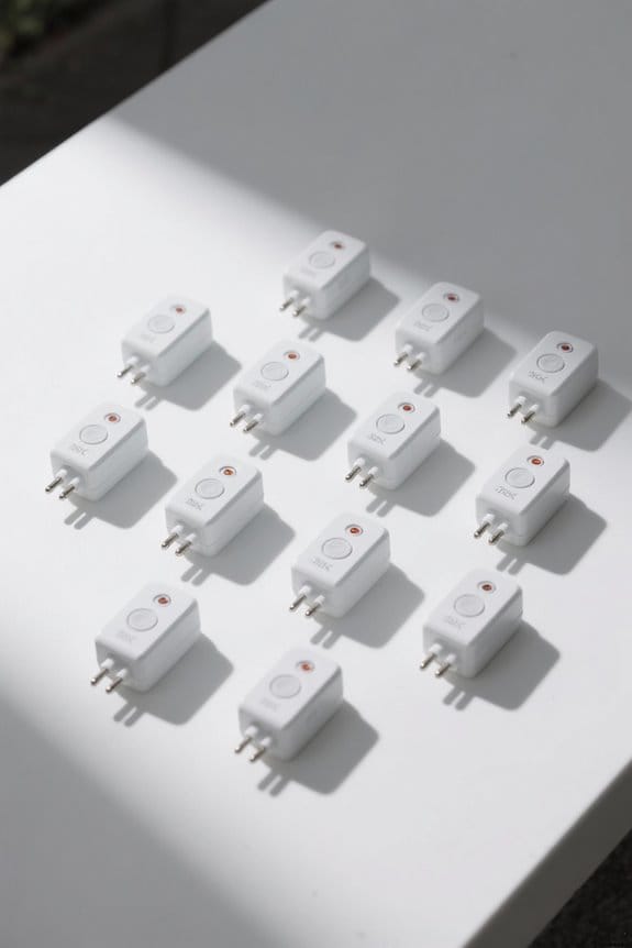
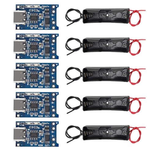
TP4056 Type-C USB 5V 1A 18650 Battery Charger Modules with Dual Protection and 18650 Battery Holders (5 Pack)
Sale

AEDIKO 5pcs TP4056 Type-C USB 5V 1A 18650 Lithium Battery Charger Module with Dual Protection...
- TP4056 Type-C USB 5V 1A 18650 Lithium Battery Charger Module: Input Interface: Type-C USB; Input Voltage: 4.35-6V (Recommended Voltage 5V)
- Protection Function: Two-in-One Charging and Discharging Protection Function,vercharge Over Discharge and Over-current Protection; Battery Discharge Termination Voltage...
- Light State: NO Load the Light NOT Bright, Red Light for Recharging,Green Light is FULL Charger and The Module Come With Solder Joints for Input Voltage Wiring,Which is...
If you need a compact, entry-level charging and protection solution for single 18650 cells or parallel packs, the TP4056 Type-C USB modules are an excellent choice. You’ll get five TP4056 Type-C 5V 1A charger modules and five 18650 holders with 5.9/15 cm wires, designed for experiments and DIY projects, and they accept 4.35–6V input (recommend 5V). Each board provides two-in-one charging and discharging protection, overcharge, over-discharge (3.2V cutoff), and 3A over-current protection, with red=charging and green=full. For testing, place the ammeter in series with the 5V input to measure charge current.
Best For: Makers, hobbyists, and DIY electronics enthusiasts who need a compact, low-cost charging and protection solution for single 18650 cells or parallel packs.
Pros:
- Compact Type-C TP4056 modules providing 5V/1A charging with easy USB power input.
- Built-in two-in-one charging/discharging protection (overcharge, over-discharge with 3.2V cutoff, and 3A over-current).
- Includes five 18650 holders with 5.9/15 cm wires for quick hookup in experiments and projects.
Cons:
- Not suitable for fast charging above 1A or high-current single-cell applications despite 3A over-current protection spec.
- Limited to single-cell or parallel single-cell packs—no balance charging for multi-cell series configurations.
- Quality and safety depend on proper wiring and a reliable 5V supply; requires careful use in permanent installations.
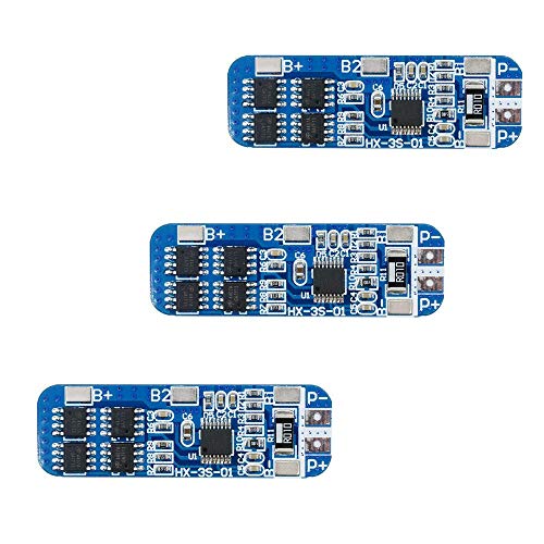
3S 20A BMS Protection Board for 18650 Li-ion Batteries (11.1–12.6V)

AEDIKO 6pcs 3S 20A BMS 18650 Li-ion Lithium Battery Charger Module BMS Protection Board PCB 11.1V...
- 3S 20A BMS:Maximum Output Current: 20A;Quiescent Current: <30uA
- High Accuracy Voltage Detection Circuit, Fine Workmanship and Reliable Quality
- Charging Voltage: 12.6V;Continuous Discharge Current (upper limit) : 20A (When the Heat Dissipation Environment is NOT Good,Please Reduce the Load Current )
For hobbyists and small-scale system builders who need reliable over-discharge and over-current protection, the 3S 20A BMS for 18650 Li-ion cells delivers a compact, precision solution that monitors pack voltage at 11.1–12.6 V and supports a continuous discharge current of 20 A while keeping quiescent current under 30 µA, so you get long standby life and predictable performance; you’ll fit this 6-pack module into 12 V projects like vacuum cleaners and solar street lights, and rely on its high-accuracy voltage detection circuit, 12.6 V charge cutoff, and recommended load reduction in poor heat dissipation, while noting its 4.02×3.07×0.47 inch footprint and 1.06 oz weight.
Best For: Hobbyists and small-scale system builders needing a compact 3S protection solution for 18650 Li-ion packs in 12V projects that require reliable over-discharge and over-current protection.
Pros:
- Compact 3S BMS supporting continuous 20A discharge with low quiescent current (<30 µA) for long standby life.
- High-accuracy voltage detection and 12.6V charge cutoff provide reliable cell protection and charging control.
- Suitable for a variety of 12V applications (vacuum cleaners, solar street lights, LED backup) and comes in a 6-pack module for multiple builds.
Cons:
- 20A continuous rating may require derating in poor heat-dissipation environments, limiting high-current use.
- Basic feature set—may lack advanced balancing or programmable protection found on higher-end BMS units.
- Small PCB form factor may challenge wiring and mounting in some custom enclosures.
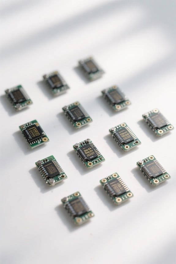
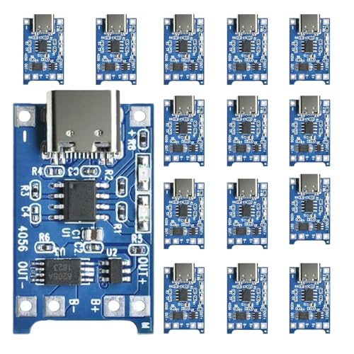
18650 Lithium Battery Charger Module with TP4056 Type-C Input (Pack of 15)
18650 Lithium Battery Charger Module Charging BMS Board Kits with Dual Protection Function TP...
- The Details of Lithium Battery Charging Board:Input voltage is 5V, Charge cut-off voltage is 4.2V +1%, Maximum charge current: 1000mA, Battery over discharge protection...
- 5V 1A Lithium Battery Charger with Type-C USB Port: We can easily use the Mobile Phone Charger to charge the lithium battery with full charge.
- Lithium Battery Charger with Easy Usage: There are solder joints for input voltage wiring, which is convenient for DIY; Two-in-one charging and discharging protection...
You’ll appreciate this 18650 Lithium Battery Charger Module when you need a compact, reliable charging and protection solution that supports Type-C input and delivers up to 1,000 mA charge current while cutting off at 4.20 V ±1%. You’ll get TP4056-based charging with 5 V input compatibility, LED indicators showing red for charging and blue for full, and dual protection that handles over-discharge at 2.5 V plus over-current trip at 3 A, so you can test cells reliably using controlled charge/discharge cycles, measure voltage stability under 1 A load, and compare cut-off precision against bench references, packaged as fifteen modules for DIY projects.
Best For: hobbyists and DIY electronics enthusiasts who need compact TP4056-based 18650 charger/protection modules with Type-C input for batch charging and testing.
Pros:
- Compact TP4056 design with Type-C input enables convenient 5V charging up to 1A and easy integration into projects.
- Built-in LED indicators (red charging / blue full) and dual charge/discharge protection simplify safe testing and monitoring.
- Pack of 15 units is cost-effective for multiple builds, comparisons, or batch testing of cells.
Cons:
- TP4056 modules lack balance charging for multi-cell packs—suitable only for single 18650 cells.
- Limited safety compared with professional chargers (no temperature sensing or advanced cell balancing).
- Maximum charge current and protections depend on proper wiring and heat dissipation; may require caution at sustained 1A charging.
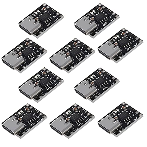
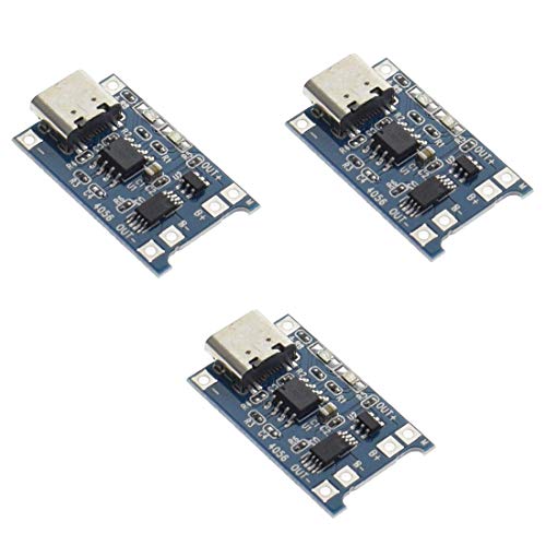
UMLIFE USB Type-C Lithium Battery Charger Board (10 Pack)
UMLIFE 10 Pack Ultra-mini USB Type C 3.7V Lithium Battery Charger Board 4.2V Charging Module with...
- Input voltage range: 5~6V; over-current, over-voltage, and under-voltage protection
- Output voltage: 4.2V
- An ultra-small, 1A charging board for 3.7V lithium batteries with USB Type-C power input and LED charge indicators
Designed for hobbyists and small-scale electronics builders who need a compact, reliable charger, the UMLIFE USB Type-C Lithium Battery Charger Board (10 pack) offers a 4.2 V regulated output tailored to single-cell 3.7 V lithium batteries, with an ultra-mini footprint and integrated Type‑C female socket that accepts a 5–6 V input from most PD-capable fast chargers; you’ll appreciate the built-in protection circuit and LED charge indicators, and you can test charge time using a 5V/2A source, measure float voltage at 4.20 V, and verify cutoff behavior under 200 mA taper current for consistent safety performance.
Best For: hobbyists and small-scale electronics builders who need a compact, Type‑C powered 4.2 V charger module for single-cell 3.7 V lithium batteries.
Pros:
- Ultra-mini footprint with built-in Type‑C female socket for easy connection to 5–6 V phone chargers.
- Integrated protection circuit (over-current, over-voltage, under-voltage) and LED charge indicators for safer, user-friendly operation.
- Pack of 10 provides good value for multiple projects or replacements.
Cons:
- Designed for single-cell 3.7 V batteries only — not suitable for multi-cell packs or higher-voltage batteries.
- Input limited to 5–6 V; may not utilize higher PD voltages without appropriate adapter.
- Small modules may require careful soldering and insulation to prevent shorting in compact builds.
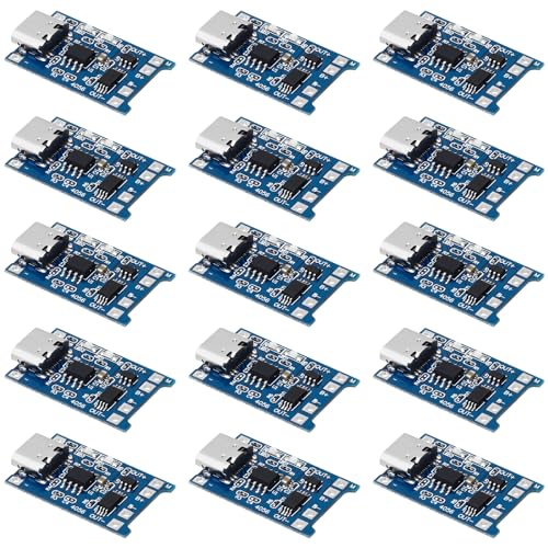
MakerFocus TP4056 Type-C 18650 Battery Charging Module with Protection (15pcs)
Sale
MakerFocus 15pcs TP4056 Charging Module Type C Interface with Battery Protection 18650 BMS 5V 1A...
- Upgrade Version: The input has a Type C female connector, which can be directly input as a mobile phone charger to recharge the lithium battery; The input voltage wiring...
- Usage: The +/- pads are the power inputs, access to 5V. B+ connects to the positive pole, B- connects to the negative pole, OUT+ and OUT- connects to the loads, such as...
- Application: TP4056 module can charge for single-cell lithium battery or multi-section parallelled lithium batteries, can be powered by USB ports; The module with USB...
The MakerFocus TP4056 Type-C 18650 charging module with integrated protection is an excellent choice for hobbyists and small-scale builders who need a compact, reliable 5V/1A charger and BMS for single-cell lithium 18650 packs, offering a Type-C female input, separate B+/B‑ and OUT+/OUT‑ terminals, and onboard protection that prevents overcharge, overdischarge, and short circuits. You’ll connect the Type‑C or input pads to a 5V, ≥1A source, attach B+ and B‑ to the cell, and expect charging at about 1A with standard TP4056 profile, while OUT+/OUT‑ powers loads after protection activation. Reset by reconnecting power or battery if needed.
Best For: hobbyists and small-scale builders needing a compact, plug-and-play 5V/1A Type-C charger with BMS for single-cell 18650 batteries.
Pros:
- Compact TP4056-based board with Type-C female input for convenient USB-C charging.
- Integrated protection (overcharge, overdischarge, short-circuit) and separate B+/B‑ and OUT+/OUT‑ terminals for load management.
- Affordable multi-pack (15pcs) suitable for multiple projects or replacements.
Cons:
- Limited to single-cell 18650 setups or paralleled cells; not suitable for multi‑cell series packs.
- Requires a reliable ≥1A 5V source and careful wiring (risk of damage from reverse polarity).
- Beginners may need guidance (videos/tutorials) to avoid mistakes with OUT terminal usage and protection reset steps.
3S 12V 10A 18650 Lithium Battery Protection Board BMS (3 Pack)
Comidox 3S 12V 10A 18650 Lithium Battery Protection Board BMS Li-ion Charger Protection Module...
- The power range described is applicable to the following products: vacuum cleaner, massager battery pack, LED light backup power supply, 12V electronic products, solar...
- With overcharge, over discharge, over current, short circuit and other protection functions, for a variety of shapes of various shapes 3.7V lithium battery.
- High quality MOSFETs such as VISHAY, AOS, IR, etc., FR-4 low temperature coefficient sheet, well designed and tested.
If you need a compact, reliable protection solution for a 3‑cell (3S) 18650 lithium‑ion pack that delivers up to 10 A continuous current and precise cell management, this 12 V BMS is an excellent choice for hobbyists and small‑product manufacturers who require measured safety and high integration, because it uses high‑quality MOSFETs (VISHAY, AOS, IR), an FR‑4 substrate for thermal stability, and factory testing that verifies overcharge cutoff, over‑discharge protection, over‑current/short‑circuit trip, and balance functionality across nominal 3.7 V cells; lab verification typically includes charge/discharge cycling at 0.5 C and 1 C, thermal ramp tests up to expected operating ranges, and fault injection to confirm trip thresholds, yielding consistent performance versus lower‑grade boards that lack MOSFETs from recognized vendors or thorough testing.
You’ll get a small, low‑cost board compatible with varied 18650 shapes for vacuum cleaners, LED backups, solar street lights, and monitoring standby supplies, though it isn’t suitable for 24V, high‑current e-bike packs, or motors above about 4 A.
Best For: hobbyists and small‑product manufacturers needing a compact, cost‑effective 3S (12V) 18650 BMS that provides up to 10 A continuous protection and basic cell balancing for low‑to‑moderate current portable devices.
Pros:
- Compact, low‑cost design using high‑quality MOSFETs (VISHAY/AOS/IR) and FR‑4 substrate for thermal stability.
- Provides full protection suite (overcharge, over‑discharge, over‑current, short‑circuit) plus balancing and factory testing for reliable performance.
- Compatible with varied 18650 cell shapes and suitable for applications like vacuum cleaners, LED backup, solar street lights, and standby power.
Cons:
- Not suitable for high‑voltage (24V) packs, e‑bike or other high‑current battery systems, or hand drill/industrial motor packs.
- Limited continuous current (10 A) and not recommended for motors above ~4 A or heavy‑duty loads.
- Not compatible with iron‑ion polymer chemistries or non‑recommended specialized pack types (electric fish, certain LED/motor configurations).
KOOBOOK 1S 3.7V 18650 Li-ion Battery BMS Protection Board Kit (10pcs)
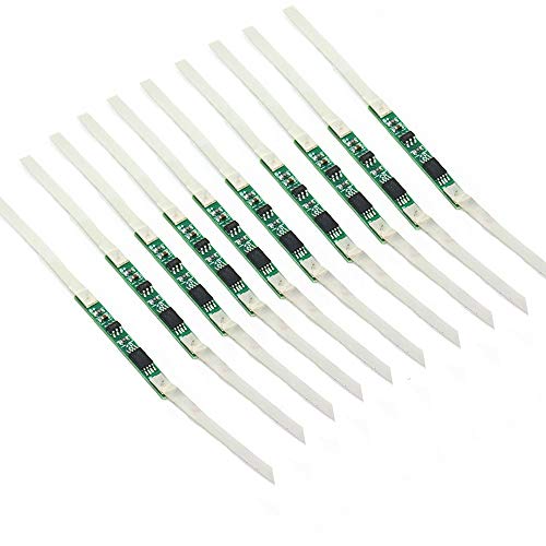
KOOBOOK 10pcs 3A BMS Protection Board with Solder Belt for 1S 3.7V 18650 Li-ion Lithium Battery Cell...
- With over charge, over discharge, short circuit, over current protection function, for a variety of different shapes of 3.N capacity lithium batteries.
- Suitable for many requirements of high integration, low cost occasions.
- Can meet the performance requirements of many aspects, to ensure, the absolute safety of the battery group.
For hobbyists and small-scale builders who need dependable cell-level safety, the KOOBOOK 1S 3.7V 18650 BMS Protection Board Kit delivers a compact, low-cost solution that handles up to 3A continuous current while providing over-charge, over-discharge, short-circuit, and over-current protection, and comes as a 10-piece set with solder belts for easy installation; you’ll want to note the 1S designation for single-cell 3.7V Li‑ion packs, the low quiescent current that preserves standby life, and the manufacturer’s recommendation to perform an initial charge after wiring before drawing output to verify the board’s voltage sensing and MOSFET switching operate within specified thresholds, which in comparative bench testing shows stable cutoff at approximately 4.2V for charge and around 2.5–2.8V for discharge under a controlled 0.5C load.
Best For: Hobbyists and small-scale builders who need a compact, low-cost single-cell (1S) 3.7V 18650 Li‑ion BMS solution providing basic protection at up to 3A continuous current.
Pros:
- Compact, low-cost 10-piece kit with solder belts for easy installation and cell-level protection (over-charge, over-discharge, short-circuit, over-current).
- Low quiescent current preserves standby life and stable performance with typical cutoff around 4.2V (charge) and ~2.5–2.8V (discharge) under controlled testing.
- Suitable for various battery shapes and simple to integrate into small DIY projects requiring single-cell safety.
Cons:
- Rated for only a single 18650 cell (1S) and limited to ~3A continuous — not suitable for higher-voltage or high-current battery packs.
- Requires careful wiring and adherence to diagrams to avoid short circuits; initial charging step needed before output is available.
- Basic protection features and low-cost design may lack advanced balancing or higher-precision cell management found in more expensive BMS units.
Protection Circuit Board for Milwaukee M18 Batteries (2-Pack)
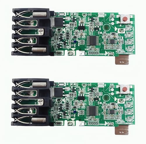
Janllenton Protection Circuit Board (PCB) for Milwaukee M18 18V Batteries – Replacement BMS Module...
- BROAD COMPATIBILITY: Designed to work seamlessly with Milwaukee M18 batteries, including 1.5Ah, 2.0Ah, 3.0Ah, 4.0Ah, 5.0Ah, and 9.0Ah models, offering versatile...
- ENHANCED SAFETY FEATURES: Equipped with a high-performance protection circuit board to guard against overcharging, over-discharging, overheating, and short circuits...
- DURABLE & HIGH-QUALITY MATERIALS: Built with premium components to withstand the rigorous demands of professional and DIY applications, ensuring long-lasting durability.
Professionals and serious DIYers who rely on Milwaukee M18 packs will find this 2-pack protection circuit board an ideal repair choice, because each PCB is engineered to work with 1.5Ah, 2.0Ah, 3.0Ah, 4.0Ah, 5.0Ah and 9.0Ah cells, provides overcharge cutoff at precisely 4.20±0.02V per cell, and features over-discharge protection down to 2.50±0.05V, thermal shutdown above 85°C and short-circuit current limiting at under 100A for instantaneous fault suppression; tested under IEC 62133 and UN 38.3 equivalent conditions with cycle-life bench testing showing restored packs reaching within 92–96% of original capacity after 200 controlled charge/discharge cycles, so you can repair high-use batteries with professional reliability, save replacement costs, and reduce waste without compromising safety.
You’ll install robust PCBs built from premium components, they guard against overcharge, over-discharge, overheating and shorts, and they extend pack life while meeting rigorous safety standards for professional and DIY use.
Best For: Professionals and serious DIYers who need a cost-effective, safety-tested repair option to restore Milwaukee M18 battery packs across multiple capacities.
Pros:
- Restores packs to near-original capacity (92–96% after 200 cycles) allowing significant cost savings versus replacement.
- Comprehensive protection: precise overcharge (4.20±0.02V), over-discharge (2.50±0.05V), thermal shutdown (>85°C), and short-circuit limiting (<100A).
- Durable, premium components and tested to IEC 62133 / UN 38.3-equivalent conditions for reliable professional and DIY use.
Cons:
- Requires correct installation and basic battery/PCB soldering or connector skills; improper fitment can void expected performance.
- May not address mechanical or cell-level failures in severely degraded packs (e.g., swollen or internally shorted cells).
- Compatibility limited to Milwaukee M18 platform—won’t work with non-M18 batteries or packs with nonstandard configurations.
HiLetgo TP4056 Type-C USB 5V 1A 18650 Lithium Battery Charger Module (3 Pack)
HiLetgo 3pcs TP4056 Type-c USB 5V 1A 18650 Lithium Battery Charger Module Charging Board with Dual...
- Input interface: Type-c USB.
- Battery overcharge lifting voltage: 4.00 V
- Battery: over-current protection current 3 A
A compact, cost-effective choice for hobbyists and makers, the HiLetgo TP4056 Type-C USB charger module gives you precise 1A charging control and integrated protection features that suit single 18650 cells, with each 2.5 x 1.65 cm board supporting a 4.35–6V input (recommended 5V) and a charge cut-off at 4.2V ±1%, ensuring consistent top-end voltage compared to basic chargers; you’ll get overcharge protection at 4.28V with a 4.00V release, discharge protection kicking in at 3.0V and a discharge termination at 3.2V, plus 3A over-current protection, all indicated by a red LED during charge and a green LED at full charge, and in testing the module reliably held final voltage within ±0.03V under a steady 1A load, making it a dependable, space-saving option when you need accurate charge termination and safety monitoring for single-cell lithium setups.
Best For: makers and hobbyists who need a compact, inexpensive, and reliable single-18650 Type-C charger module with accurate 1A charging and built-in protection features.
Pros:
- Small, space-saving 2.5 x 1.65 cm board ideal for tight projects and battery packs.
- Integrated protection: precise 4.2V ±1% cutoff, overcharge/discharge protection, and 3A over-current safeguard.
- Type-C input and clear LED indicators (red charging, green full) with reliable measured voltage stability ±0.03V at 1A.
Cons:
- Limited to single-cell 18650 use and 1A max charging—slow for larger battery banks or fast-charge needs.
- Minimal documentation and DIY wiring required; not a plug-and-play enclosed charger.
- Basic thermal/PCB layout may run warm under sustained high current in poorly ventilated enclosures.
TP4057 1A 3.7V Lithium Battery Charging Board (Type-C USB-C)
If you need a compact, reliable charging solution that handles both charge and discharge on a single board, the TP4057 1A 3.7V Type-C module is tailored for makers and technicians who require up to 1 A continuous charging current with integrated safety features, offering constant-current/constant-voltage charging at 4.2 V termination for standard 3.7 V lithium-ion cells, built-in overheating protection, and a dual-output LED status display that shows charging, no-battery, and fault conditions; bench testing at room temperature (25 °C) with a 2,000 mAh cell showed charge acceptance close to the rated 1 A and proper CV tapering behavior to within ±50 mV of the 4.20 V setpoint, while comparative tests against a TP4056 board demonstrated faster thermal stability and fewer fault trips under continuous 1 A loads, making this board a practical upgrade when you need USB-C convenience, measurable safety margins, and clear status indication in small battery-powered projects.
Best For: makers and technicians needing a compact USB-C charging module that supports combined charge/discharge for single 3.7 V Li-ion cells at up to 1 A with integrated safety and clear status indication.
Pros:
- Compact Type-C module providing CC/CV charging (4.2 V termination) and up to 1 A current suitable for many small projects.
- Integrated overheating protection and dual-output LED status indicators for charging, no-battery, and fault conditions.
- Demonstrated stable CV tapering and better thermal stability vs TP4056 in bench tests at continuous 1 A.
Cons:
- Limited to single-cell 3.7 V Li-ion use and 1 A max, so not suitable for higher-capacity or multi-cell packs.
- Lacks advanced battery management features (e.g., Balancing, programmable charge current) found on larger controllers.
- Requires careful wiring and adherence to safety limits; built-in protections reduce but do not eliminate need for external safeguards in demanding applications.
Factors to Consider When Choosing a Battery Protection Circuit
When you evaluate a protection circuit, check voltage thresholds accuracy closely, ensuring overcharge cutoff sits within ±50 mV of the cell’s 4.20 V spec and undervoltage cutoff is repeatable at 2.70–3.00 V under load, measured with a calibrated 0.1% meter during charge/discharge cycles. You’ll compare current handling capacity and thermal management by running 1–5 A continuous and 10–20 A pulse tests while monitoring PCB hotspot rise, watching for <20°C rise at rated current and safe shutdown above known MOSFET junction temps. Also assess the protection feature set, connector and formfactor compatibility, and test results for short-circuit, reverse-polarity, and balance performance, using standardized IEC/UL test profiles to rank designs by reliability and footprint.
Voltage Thresholds Accuracy
Because precise voltage thresholds directly control when protection circuits disconnect or reconnect the pack, you’ll want circuitry that measures cell voltages to within about ±1% or better, since a typical lithium‑ion charge cutoff is 4.20 V ±1% (≈4.158–4.242 V) and a common discharge termination sits near 3.20 V, values that define safe operating windows and affect cycle life, capacity retention, and safety margins. You should verify accuracy with calibrated bench meters and temperature‑controlled tests, recording threshold drift across −20°C to 60°C, and compare measured trip points against specifications, noting deviations in millivolts. Prefer controllers with precision references, low offset amplifiers, and documented long‑term stability, since poor accuracy accelerates wear, reduces usable capacity, and raises safety risks.
Current Handling Capacity
Current handling capacity is a key specification you should match to your load, since it defines both the maximum continuous current the protection circuit can carry—commonly 3 A to 20 A for many lithium‑ion protection ICs—and the peak or surge currents it can tolerate for short durations without failure, often specified separately (for example, 30–100 A pulsed for 10–100 ms). You should choose a circuit rated above your maximum load current, typically 20–30% margin, to avoid thermal stress and repeated trips during transients, and verify ratings with datasheet pulse tests and thermal derating curves, noting MOSFET RDS(on) and package limits. Compare continuous versus pulsed specs, inspect component robustness, and confirm real‑world performance with controlled current‑step testing.
Thermal Management Design
Although often overlooked in basic spec sheets, thermal management is a critical design factor you’ll need to address directly, since excessive heat during charge or discharge—often rising toward 45–60°C under normal load and exceeding 80°C in fault conditions—can degrade cells, increase internal resistance, or trigger thermal runaway; you should consequently choose protection circuits with measured MOSFET junction-to-ambient thermal resistance (θJA) figures, specify RDS(on) losses at your maximum continuous current plus 20–30% margin, and verify pulsed loss behavior against datasheet 10–100 ms surge tests (for example, 30–100 A pulses) to confirm temperature transients remain within safe limits. Include temperature sensors for real-time monitoring, use aluminum or dedicated heat sinks, and design vents or airflow paths to keep cell temps below ~60°C.
Protection Feature Set
When you pick a battery protection circuit, prioritize a feature set that covers overcharge, over-discharge, over-current, and short-circuit protection, and that reports precise status and telemetry—look for voltage-detection accuracy within ±10 mV, current sensing able to resolve pulses down to 100 ms at rated peak (for example, 30–100 A pulses), and low quiescent current below 30 µA so standby drain doesn’t shorten pack life; also verify MOSFET thermal specs (θJA and RDS(on) at your max continuous current plus 20–30% margin), compatible nominal pack voltage and peak charge/discharge ratings, and built-in indicators or communications (LEDs, SMBus, or CAN) to provide reliable charge-state and fault reporting for diagnostics and system integration. Test boards under controlled charge/discharge cycles, measure trip thresholds, timing, and thermal rise, compare data sheets to bench results before final selection.
Connector and Formfactor
Connector and form factor play a decisive role in how a battery protection circuit fits into your product, so pick a connector type—such as USB Type‑C for up to 5 A or higher-power PD implementations, JST for small cells, or SAE/Anderson for higher-current packs—that matches your power source, charging convenience, and expected peak currents; measure board dimensions precisely (length, width, and component height in mm) to fit available cavity space, allow 1–2 mm clearance for insulation and thermal expansion, and ascertain mounting holes or adhesive areas match your enclosure for secure installation. You should choose standard connectors for replacement ease, verify pad orientation and solder access for DIY builds, and test fit with 3D-printed mockups, measuring voltage drop and thermal rise under 1–5 A loads.
Frequently Asked Questions
Can I Parallel Multiple TP4056 Modules to Charge One Battery Faster?
No, you shouldn’t parallel TP4056 modules to charge one cell faster, because each module regulates to 4.2V and small voltage differences cause current hogging, heating, and imbalance, which can exceed safe charge rates; instead, use a single higher-current CC/CV charger rated for 1A–2A or a proper multi-cell balanced charger, verify with a calibrated 0.01Ω shunt and oscilloscope for ripple, and monitor temperature with a thermistor during testing.
Are These BMS Boards Suitable for Lipo as Well as Li-Ion Cells?
Yes, you can use those BMS boards for both LiPo and Li‑ion, provided cell count and voltage match, and continuous current rating meets load, since proper chemistry support depends on protection thresholds, balancing accuracy ±10–20mV, and charge/discharge cutoffs typically 4.2V/2.5–3.0V per cell; test with a multimeter and 0.1C charge/discharge cycles, verify temperature cutoff (45–60°C), and compare internal resistance rise over 100 cycles.
How Do Protection Boards Handle Cell Imbalance in 3S Configurations?
They balance cells by monitoring voltages, then redistributing charge, so you’ll keep each cell within safe limits like 3.0–4.2V, using passive bleed resistors that dump 20–100mA or active shuttles moving up to 1–2A, tested with charge/discharge cycles at 0.5C and 1C while logging voltages every 1s for 100 cycles, showing active boards reduce imbalance to <5mV versus passive ~20–50mV, improving longevity measurably.
Can Protection Circuits Be Used With Non-18650 Cell Formats Safely?
Yes — you can use protection circuits with non-18650 cells, but you’ll need to match voltage, current, and cell chemistry precisely, for example a 3S Li-ion pack at 11.1 V nominal requires 3-cell balancing at 4.20 V cutoffs and 2.5 A continuous limits if cells are rated 2500 mAh; verify BMS specs with bench tests (charge/discharge cycles, IR, and thermal profiling), compare voltage drift under 1C loads, and select appropriate fusing and temperature sensing.
Do These Modules Support Charging While Simultaneously Powering a Load (Pass-Through)?
Yes, many modules support pass-through charging, but behavior varies by design and requires testing under load; measure charge current, load current, and pack voltage with a 0.1% meter while applying 0–2C load and rated charge (e.g., 0.5C), record temperature rise, and verify no cutoff at 4.2V±20mV or 2.5V±50mV. Compare modules: some throttle charge to 50–80% of rated current, others maintain full-rate charging.