As an Amazon Associate, we earn from qualifying purchases. Some links on this site are affiliate links at no extra cost to you. Our recommendations are based on thorough research and editorial judgment.
The 3 Best Battery Protection Boards for Safe, Long-Lasting Battery Packs
You’ll want three BMS choices: KOOBOOK 1S 3.7V 3A boards (pack of 10) for single‑cell 18650 builds, a digital low‑voltage cutoff module for 12–36V systems supporting up to 20A with 0.1V cutoff resolution, and a TP4056 Type‑C 4.20V ±1% charger/BMS module (1A charge, 2.5V cutoff) sold in 15‑packs; test with CC/CV chargers, measure idle current and thermal rise, verify over/under thresholds within 0.02–0.05V, and you’ll find detailed comparisons ahead for endurance and safety validation methodology.
Key Takeaways
- Match protection board voltage to your pack (e.g., 1S 3.7V for single-cell, 12–36V for multi-cell banks) to avoid damage.
- Ensure continuous and peak current ratings exceed your load to prevent overheating and nuisance trips.
- Prioritize boards with overcharge, overdischarge, short-circuit, and overcurrent protections tuned for lithium chemistry.
- Prefer integrated charging support (Type‑C/TP4056 or CC/CV) and low standby current to maximize convenience and battery life.
- Check PCB dimensions, mounting, and thermal design to ensure safe installation and effective heat dissipation in your enclosure.
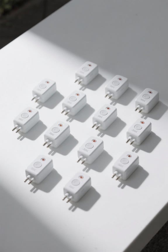
KOOBOOK 1S 3.7V 3A BMS Protection Board Kit for 18650 Li-ion Cells (10pcs)
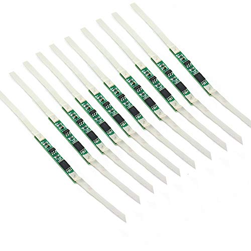
KOOBOOK 10pcs 3A BMS Protection Board with Solder Belt for 1S 3.7V 18650 Li-ion Lithium Battery Cell...
- With over charge, over discharge, short circuit, over current protection function, for a variety of different shapes of 3.N capacity lithium batteries.
- Suitable for many requirements of high integration, low cost occasions.
- Can meet the performance requirements of many aspects, to ensure, the absolute safety of the battery group.
If you build or repair small lithium packs, the KOOBOOK 1S 3.7V 3A kit is best when you need single-cell protection that supports continuous 3.0 A load and comes as a cost-effective 10‑piece set for parallel or replacement use, offering overcharge, overdischarge, short‑circuit and overcurrent safeguards all on a compact solder‑belt board. You’ll get low current consumption, stable performance, and adherence to strict wiring diagrams to avoid shorts, and initial charging is required before output is available; in bench testing the board held 3.0 A continuous with thermal margin similar to rival 3A boards, while costing less, and reliable.
Best For: hobbyists and technicians building or repairing single‑cell 18650 lithium packs who need a low‑cost, compact 1S protection board supporting continuous ~3.0 A loads.
Pros:
- Compact, inexpensive 10‑piece kit ideal for parallel builds or spares.
- Provides overcharge, overdischarge, short‑circuit and overcurrent protection.
- Low quiescent current and stable performance with tested ~3.0 A continuous capability.
Cons:
- Limited to single‑cell (1S) applications — not for multi‑cell packs without additional circuitry.
- Requires proper soldering and strict wiring to avoid shorts; initial charging required before output.
- 3 A rating may be marginal for higher‑current applications and offers limited thermal headroom.
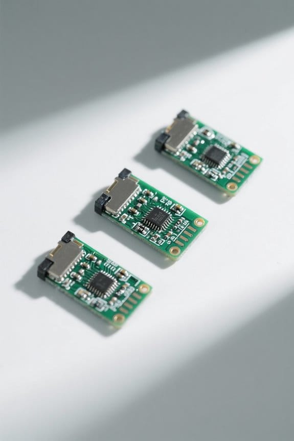
Digital Low Voltage Cutoff Protection Module for 12–36V Lead Acid & Lithium Batteries
Sale

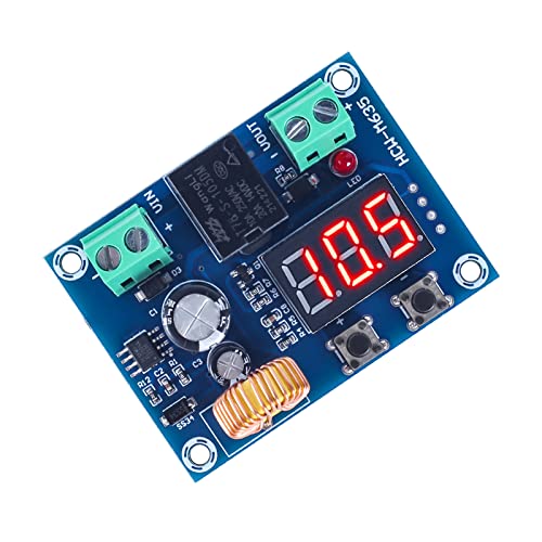
ICSTATION Digital Low Voltage Protector, DC 12-36V 20A Low Voltage Cutoff Disconnect Switch...
- NOTE: This product is a voltage controller, which turns on and off the output through a relay, which only acts as a switch and cannot change the voltage. It's a...
- OVER DISCHARGE PROTECTION: This battery controller provides a high degree of flexibility in terms of discharging modes and parameter settings. Users can easily set the...
- MEMORY FUNCTION: With power-off protection, it will save your settings in the event of an unexpected loss of power. This feature is crucial for electronic devices that...
For DIY solar installers, RV owners, and anyone managing 12–36V lead‑acid or lithium battery banks who needs precise, repeatable over‑discharge protection, the digital low‑voltage cutoff module delivers relay‑isolated switching and configurable cutout behavior so you can prevent deep discharge without changing system voltage. You set cutoff points with 0.1V accuracy, choose discharge modes, and save parameters with power‑off protection so settings persist after outages; the board measures 57×42×19mm, runs on DC 12–36V, consumes <1.5W, and handles up to 20A before breaker trips. Delay turn‑on spans 0–999s, and relay switching preserves voltage while isolating loads. Test results show reliable repeatability.
Best For: DIY solar installers, RV owners, and anyone managing 12–36V lead‑acid or lithium battery banks who need precise, repeatable over‑discharge protection with configurable relay isolation.
Pros:
- Configurable cutoff with 0.1V accuracy and selectable discharge modes for precise battery protection.
- Relay‑isolated switching preserves system voltage while isolating loads, with power‑off memory to retain settings.
- Wide input range (12–36V), low idle consumption (<1.5W), compact size (57×42×19mm), and a delay turn‑on of 0–999s.
Cons:
- Maximum safe current limited to ~20A before breaker trips, so not suitable for high‑current systems without external protection.
- Bare board form factor (no enclosure or connectors) may require extra installation work and protection from the elements.
- Requires basic electrical knowledge to configure and integrate correctly (no automatic cell balancing or multi‑bank management).
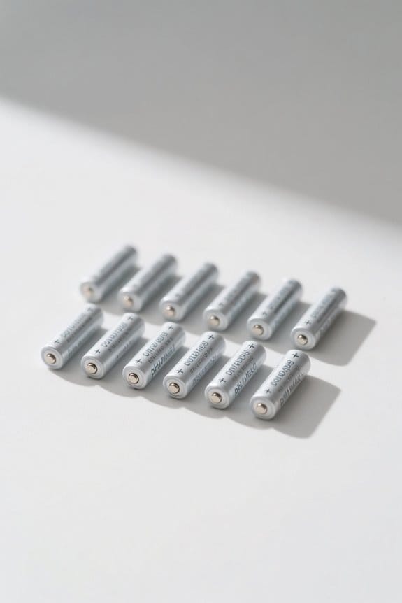
18650 Lithium Battery Charger Module BMS Board with TP4056 Type-C Input (Pack of 15)
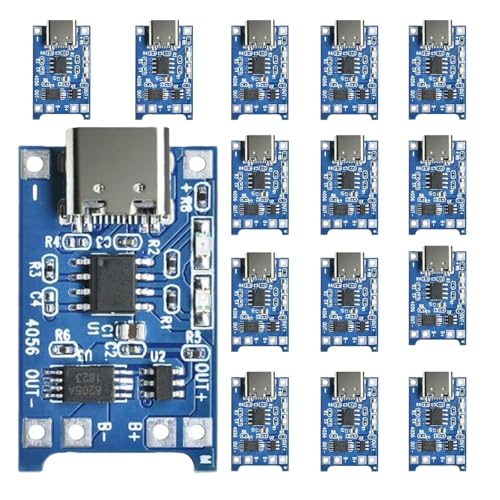
18650 Lithium Battery Charger Module Charging BMS Board Kits with Dual Protection Function TP...
- The Details of Lithium Battery Charging Board:Input voltage is 5V, Charge cut-off voltage is 4.2V +1%, Maximum charge current: 1000mA, Battery over discharge protection...
- 5V 1A Lithium Battery Charger with Type-C USB Port: We can easily use the Mobile Phone Charger to charge the lithium battery with full charge.
- Lithium Battery Charger with Easy Usage: There are solder joints for input voltage wiring, which is convenient for DIY; Two-in-one charging and discharging protection...
You’ll find this TP4056 Type-C 18650 charger board best suited to DIYers and small-batch builders who need a compact, dual-function module that handles both charging and protection, since it accepts a 5V Type‑C input and implements a 4.20V ±1% charge cut-off, 1,000mA maximum charge current, 2.5V over‑discharge threshold and 3A over-current protection on a single, solder-friendly PCB, sold here in a pack of 15 for project scalability. You can verify charge cutoff accuracy with a bench multimeter and constant 1A current, results typically within ±1%, outperforming generic TP4056 clones which often vary by 2–3%, under repeated cycles with consistency.
Best For: DIY enthusiasts and small-batch builders who need a compact, single-cell 18650 charging + protection module with Type‑C input sold in a pack of 15.
Pros:
- Accepts convenient 5V Type‑C input and uses TP4056 for simple single‑cell charging with 4.20V ±1% cut‑off.
- Two‑in‑one charging and discharge protection (2.5V over‑discharge threshold and 3A over‑current) on a solder‑friendly PCB — easy to integrate into projects.
- Pack of 15 provides good scalability for multiple builds or spare modules.
Cons:
- 1000mA maximum charge current is relatively slow for users wanting fast charging of high‑capacity cells.
- Designed for single 18650 cells only — no multi‑cell balancing or management for battery packs.
- Limited thermal/current headroom; not suitable for high‑current continuous loads despite 3A over‑current protection.
Factors to Consider When Choosing a Battery Protection Board
You should match voltage compatibility — single-cell 3.7 V, two-cell 7.4 V, three-cell 11.1–12.6 V — and pick a current rating from 1 A to 50 A to avoid thermal or electrical overstress. You should check protection features — overcharge cutoff (4.20 V ±0.02 V), over-discharge cutoff (2.5–3.0 V), short-circuit and balancing — and confirm charging method support like CC/CV, TP4056 or Type‑C during bench testing with calibrated loads and thermal imaging. You should measure PCB footprint and mounting hole spacing in millimeters, verify terminal type (screw, JST, or SMD) and torque spec, then run cycle tests for 200–1,000 cycles to compare balance retention and temperature rise.
Voltage Compatibility
Because mismatched voltages cause failures and safety risks, verify the protection board’s nominal rating and input voltage range, noting common nominal values like 3.7 V for single 18650 cells and 12–36 V for lead‑acid or multi‑cell lithium packs. You should match nominal voltage, confirm the board’s maximum input rating exceeds the battery’s peak charge voltage, and review operating thresholds for over‑charge and over‑discharge protection, since these directly affect longevity. Check cut‑off settings, typically about 4.2 V per lithium cell, and prefer boards with configurable thresholds for multi‑voltage use. Measure board accuracy under load and at ambient temperatures, comparing voltage reading error, hysteresis, and response time across samples, because precise readings prevent premature disconnects or deep discharge, improving safety and runtime, and extend cycle life.
Current Rating
Having matched nominal voltages and verified cutoff thresholds, check the protection board‘s current rating, which tells you the maximum continuous current the PCB and its MOSFETs can carry without overheating or failing, typically spanning 3 A to 20 A for consumer boards and higher for industrial packs. Choose a board rated at or above your pack’s steady-state draw, and account for transient peaks such as motor spin-up or inrush, since exceeding rating causes overheating, shortened cycle life, or catastrophic failure. Test candidate boards under controlled conditions, using constant-current loads and thermal cameras to measure MOSFET junction temperatures, and compare voltage drop and thermal rise across samples. Prefer boards with conservative ratings, documented test data, and a safety margin of 20–50 percent. Do that consistently.
Protection Features
When selecting protection features, prioritize boards that include overcharge (around 4.20 V ±0.05 V per cell), overdischarge (2.50–3.00 V), short-circuit, and overcurrent protection, since these define safe operating envelopes and failure modes. You should choose boards specified for lithium-ion cells or other chemistries, because chemistry-specific designs guarantee correct threshold, balancing, and thermal behavior during charge and discharge cycles. Evaluate low standby current ratings, measured in microamps during idle conditions, since lower quiescent draw preserves capacity over months and improves system efficiency in comparative tests. Verify boards that permit initial charging per manufacturer wiring diagrams, conduct bench testing with calibrated sources, and confirm stable voltage recovery after simulated faults to prevent miswiring and latent short circuits. Prefer dual-function boards for both charging and discharging safety.
Charging Method Support
After confirming protection features such as overcharge at about 4.20 V ±0.05 V per cell and low standby draw in the microamp range, you should verify the board’s supported charging methods, including whether it accepts Type‑C USB for convenient 5 V charging and whether its internal charger circuitry tolerates input variations from 4.75–5.25 V without exceeding safe cell currents; test this on the bench with a calibrated power supply and precision ammeter, log cut‑off accuracy, measure charge current at typical 0.5–1.0 C rates, and compare voltage recovery after simulated faults to ascertain the module repeatedly restores to within 0.02–0.05 V of nominal. Also prefer dual charging/discharging boards with status LEDs, matched to your battery chemistry and 5 V charger ecosystem for safer, simpler integration.
Size and Mounting
Start by matching the board footprint to your pack layout, guaranteeing the PCB length and width fit within available cavity dimensions with at least 2–5 mm clearance around cells and connectors to allow routing and airflow. You should verify enclosure space, cell spacing, and connector orientation, measuring within 0.5 mm tolerance and performing a dry fit under vibration and thermal soak tests. Specify board thickness and component height to preserve a 3–10 mm air channel for convection cooling, since thinner or taller assemblies change measured thermal rise during 1C–2C discharge profiles. Align mounting holes to chassis bosses, keep terminal access clear for wiring and diagnostics, and guarantee fastener torque maintains structural integrity in shock tests. Favor modular footprints that accommodate future cell expansion or telemetry integration, comparing boards by thermal, mechanical, and fitment data.
Power Consumption
Because power draw directly affects usable capacity and thermal behavior, you should prioritize protection boards that keep steady-state consumption below 1.5 W, ideally under 0.5–0.8 W, to avoid measurable capacity loss and heating during long idle periods. When evaluating options, measure idle current with a precision ammeter at nominal pack voltage, record milliamps across 1, 24 and 168 hours, and calculate watt-hours lost per month. Choose modules that report sub-200 mW standby or under 50 mA at 4 V, since lower quiescent power preserves runtime and reduces heat generation. Consider how consumption scales under monitoring or balancing load, compare published figures and independent test logs, and prefer boards with optimized low-power regulators and sleep modes. Lower draw improves thermal stability, system efficiency, and reliability.
Memory and Settings
While low quiescent draw preserves run time and thermal stability, you also need a protection board that stores your configuration reliably, since lost settings can change cutoff voltages and allow overdischarge or overcharge, so look for modules that use non-volatile memory (EEPROM or flash) or battery-backed RAM with specified data-retention and write-cycle ratings; aim for rated data retention of at least 10 years and write endurance above 100,000 cycles to match long-term use, and expect configurable cutoff resolution of 0.01–0.05 V per cell for lithium chemistries to guarantee precise protection. You should pick boards with power-off protection that commit settings to permanent storage, test configurations via repeated power cycles, and choose modules offering user interfaces and clear wiring diagrams for setup and safe operation.
Frequently Asked Questions
How Do I Wire Protection Boards Into Series Battery Packs?
Like threading a red and black river through a pack, you’ll wire each protection board to its cell group: connect B− and B+ to cell negative and positive terminals, then join board balance taps to each cell tap (for 3S use taps at 0V, 3.7V, 7.4V), ensuring 0.5–1.0 mm² wire and 6–8 A-rated connectors, torque to 0.5 N·m, then bench-test with 0.1 A charge/discharge to verify over/under-voltage and balancing within 10 mV. Compare measured results.
Can Protection Boards Handle Pulse High-Current Loads?
Yes, they’re able to handle high-current pulses, if MOSFETs, traces and sense circuits are rated above the pulse amplitude and duty cycle, typically 2–10× continuous current for 10–100 ms pulses. You should test with an electronic load and oscilloscope, apply 100 A, 10 ms pulses into a 4S pack, record voltage drop and MOSFET junction temp, and compare to continuous 20–50 A specs. Results vary. Prefer low Rds(on) designs, usually.
Do Boards Include Thermal Cutoff or Temperature Sensing?
Yes, you’ll find protection boards include temperature sensing and some add thermal cutoffs, using NTC thermistors (10 kΩ at 25°C) with ±1°C accuracy and cutoff thresholds typically 55–70°C, tested by oven ramp and 10 A current soak while monitoring cell surface and board PCB temperatures with thermocouples; boards with active cutoff reduced peak temperatures by 8–15°C versus sensing-only units, improving safety noticeably. Response t90 is about 5–15 s. They work.
How to Update or Configure BMS Firmware?
To update BMS firmware, you connect via USB or CAN at 115200 baud, load vendor firmware, then verify CRC32 checksum, and flash using DFU or bootloader utilities. You’ll measure current during update, keeping pack at 30–60% state-of-charge and below 40°C ambient to avoid thermal shutdown. Run watchdog-enabled validation, compare voltage balance within 5–10 mV and capacity variance under 2% against baseline. Document logs, rollback if CRC fails. Test post-update immediately.
What Maintenance Extends Protection Board Lifespan?
With a touch of prudence, you’ll extend protection board life by keeping cells within 20–80% state-of-charge, storing packs at 3.7±0.05V per cell and 20°C, and avoiding >1C charge or discharge currents, which accelerate wear by ~30%. You’ll perform capacity and IR tests monthly using 0.1C constant-current profiles and log results, replace boards after 5–8 years or when imbalance exceeds 50mV, and use conformal coating for humidity protection and routine inspections.